|
|
 |
|
|
|

|
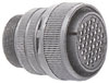
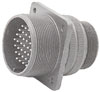
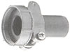
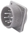
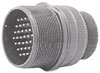
5015-Type Circular Connectors |
|
|
|
|
Specifications
|
|
|
|
Although the AS-5015 series originally intended for use on military type equipment, this series is intended for non-military applications where the connector qualities of rugged design, reliability, economic cost and intermatebility are important. This connector series is not QPL'd.
|
|
|
|
|
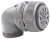
MATING GUIDE
|
|
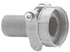
Strain relief
|
Plug
|
Receptacle
|
Strain relief
|
|
300/AS3057 & 300/AS3420 |
300/AS3106
300/AS3108 |
300/AS3100 |
300/AS3057 & 300/AS3420 |
|
300/AS3102 |
|
300/AS3101 |
|
APPLICATION
|
|
Communication equipment, transporting carriers, vessels, railroad, aircraft related equipment, industrial devices and machines, machine tools, measurement equipment, computer, petroleum and geophysical equipment.
|
|
|
|
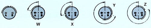
Threaded Coupling and Uncoupling
|
|
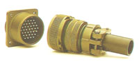 |
The plug can be coupled or uncoupled from the receptacle by simply turning the coupling nut on the plug. No special tools are required.
|
|
|
|
|
|
Contact type:
|
Alternate insert position:
|
|
P - male
S - female
|
 |
|
|
|
|
|
CONTACT CURRENT CAPACITY
|
|
The rated current of a connector will change depending on the number of contacts composing the connector and also the contact size. The table below shows the maximum permissible value per contact when assembled in an insulator.
|
|
Contact size
|
Diameter of the contacting part of pin contact
|
Current Capacity (Amps)
|
|
Contact unit
|
Assembled in insulator
|
|
#16
|
0.063" (1.6mm)
|
22
|
13
|
|
#12
|
0.094" (2.4mm)
|
41
|
23
|
|
#8
|
0.142" (3.6mm)
|
73
|
46
|
|
#4
|
0.224" (5.7mm)
|
135
|
80
|
|
#0
|
0.358" (9.1mm)
|
245
|
150
|
|
|
|
VOLTAGE RATING
|
|
Classification code
|
Test Voltage (RMS)
|
Operating Voltage
|
Air Spacing Nominal
|
Creepage Distance Nominal
|
|
DC
|
AC (RMS)
|
|
INST
|
1000
|
250
|
200
|
-
|
0.063" (1.6mm)
|
|
A
|
2000
|
700
|
500
|
0.063" (1.6mm)
|
0.126" (3.2mm)
|
|
D
|
2800
|
1250
|
900
|
0.126" (3.2mm)
|
0.189" (4.8mm)
|
|
E
|
3500
|
1750
|
1250
|
0.189" (4.8mm)
|
0.252" (6.4mm)
|
|
B
|
4500
|
2450
|
1750
|
0.252" (6.4mm)
|
0.311" (7.9mm)
|
|
C
|
7000
|
4200
|
3000
|
0.311" (7.9mm)
|
1.0" (25.4mm)
|
|
|
|
Insulation Resistance:
|
Temperature Range:
|
Humidity:
|
|
5,000 MOhm minimum at 25°C
|
-50°C to +125°C
|
Relative Humidity: 95% ± 3%
Temperature: 71°C± 2°C
Time: 14 days
|
|
Durability:
|
Thermal Shock:
|
|
500 mating/unmating operations
|
MIL-STD-202 Method 107
|
|
Vibration:
|
Shock, Electrical:
|
Salt Spray:
|
|
MIL-STD-1344 Method 2005. 10~500 Hz or 10G units
|
1/2 sine wave Transient shock impulses of 50G units
|
MIL-STD-1344 Method 1001
|
|
Sweeptime: 15 minutes
|
Time: 11±1msec
|
Salt solution: 5%
|
|
Test current: 100 mA
|
Test current: 100 mA
|
Time: 48 hours
|
|
|
|
Connector Egaging/Separation Forces
|
Compatible Wire Size
|
|
16 Contacts
|
2 kg min
|
48 kg max
|
Contact
|
Applicable Wire Size
|
|
12 Contacts
|
3 kg min
|
80 kg max
|
Size
|
Solder pot diameter
|
Wire size (AWG)
|
Conductor cross-section area
|
|
8 Contacts
|
5 kg min
|
160 kg max
|
# 16
|
0.073" (1.85mm)
|
16 ~ 22
|
1.25 sq. mm max
|
|
4 Contacts
|
10 kg min
|
240 kg max
|
# 12
|
0.116" (2.95mm)
|
12 ~ 14
|
3.5 sq. mm max
|
|
0 Contacts
|
15 kg min
|
320 kg max
|
# 8
|
0.209" (5.31mm)
|
8 ~ 10
|
8 sq. mm max
|
|
|
# 4
|
0.333" (8.45mm)
|
4 ~ 6
|
22 sq. mm max
|
|
# 0
|
0.469" (11.91mm)
|
0 ~ 2
|
50 sq. mm max
|
|
|
|
Material and Finish
|
|
Shell:
|
Aluminum alloy Die-Casting, oliver drab chromate over cadmium or Zinc plating
|
|
Insulator:
|
Polyester molding Compound & polychloroprene rubber ('A" class only)
|
|
Contacts:
|
Copper alloy Brass, 100 minches Silver plating
|
|
Retention Clip:
|
Heat treated beryllium copper
|
|
|
|
|
|

|
Alpha Center
351 Irving Drive, Oxnard, CA 93030, USA
|
|
©2021 Alpha Products, Inc. All rights reserved.
|
|
|